Congratulations to Yunqian who was selected as one of the Best Presentation Awards in IPIN 2024 for his paper
Color Marker Detection - Software and Usage
Last updated: 12/2/12
Introduction
This page contains links to software for color marker detection and instructions for its usage. The software implements the algorithm described in:
. 2011. Robust real-time detection of multi-color markers on a cell phone. Journal of Real-Time Image Processing. 6
You are allowed to download and use the software under the terms of the GNU General Public License.
What to download
To implement the classifier, you will need the following files:
- CMDetect.cpp and CMDetect.hpp : the detection engine
- main.cpp : an example of how to use the detector
- CMUserPars.xml : contains user-defined parameters
- DesignPars.xml : an example of parameter file automatically generated by the Matlab design code
To design a classifier, you will need the following Matlab files:
- CreateTMI.m : a utility for interactive labeling of images
- Run2DClassifiersComputation.m : the script that does all the design work. It calls Compute2DClassifiers.m (the actual design engine) and CreateXMLTable.m (which writes the results in an xml file that is read by CMDetect.cpp, such as DesignPars.xml above)
In addition, to design a classifier you will need two sets of training images: one set containing images the color marker, and one "background" set without the color marker. Later I will explain how to obtain good training images. To get you started, here are some sample training images:
and here are some simple background images:
You should place the background images in their own folder.
Note: if you prefer, here you can download all of the files linked above.
How to quickly test it
You should create a project with main.cpp, CMDetect.cpp and CMDetect.hpp, and link it against the OpenCV libraries libopencv_core and libopencv_highgui. (Note that OpenCV is only used in main.cpp - CMDetect does not use any OpenCV functions.) In addition, you will need the library libxml2.
Write the pathnames of the files CMUserPars.xml, DesignPars.xml and MarkerImage0.png in your system at the beginning of main.cpp (lines 19, 22 and 32). If everything works well, when you run it a window should pop up with the image of the marker filled in yellow, with two blue rectangles at the edge of the marker and a blue square at the center, and the five keypoints marked by red circles.
Note that main.cpp gives you the option to load an image file (when READ_FROM_FILE is defined) or to read images from your computer's camera.
What it does
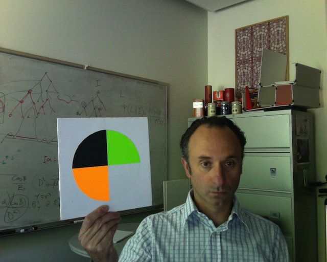
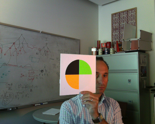
The classifier detects one or more types of color marker in the image. The color markers are pie-shaped with four color sectors - here is a sample for you to print. (Rather than printing it, I create a collage with diferent opaque colored paper for the different sectors of the marker - this reduces specular reflection, a phenomenon that can fool the detector.) You can change the colors if you like, but remember - each time you change the colors, you will need to re-train the classifier.
You can obtain different color markers ID by permuting the order of the four colors in the marker (up to a total of 24 different IDs). To inform the detector about the ID of the marker you are looking for (i.e. the order of the color sectors in your marker), you specify the permutation ID in CMUserParams.xml. More details in the next section. You can also tell the detector to search for more than one permutations IDs (for example, if you have several markers in the scene and you want to the detector only to find a few selected ones.) However, note that the detector returns the location of just one marker, even if multiple markers for the desired ID(s) are visible.
A marker is thus characterized by the order of its color sectors. The marker needs to be seen upside up - if you rotate the marker, it will correspond to another permutation ID!
How to use it
The system parameters are stored in two xml files. The first file (DesignPars.xml) contains the classifier parameters. This is automatically generated by our Matlab code based on the training images - more details in the next section. You should never edit this file yourself. The second file (CMUserPars.xml) contains run-time parameters, that you can specify by editing the xml file. In particular, you may need to change the value for these fields:
- CascadeLength : The length of the cascade of 2-D tests for the classifier - see article. This is a number smaller than or equal to 18. Smaller values result in higher detection rate but more false alarms, and vice-versa. (When debugging the system, you may choose a small value for CascadeLength - e.g. 5. For a well designed classifier, you should be able to set CascadeLength to 15 or higher, making it bullet-proof against false alarms.)
- NumberOfPermutations : This is the number of different color permutation IDs that the detector will search for. The ordered list of permutations is contained in the PermutationIndex fields. More precisely: the detector will look only for markers with permutation IDs equal to the first NumberOfPermutations entries in the PermutationIndex list. For example, if you are searching for a marker with one specific permutation ID (this is by far the most common situation), you would set NumberOfPermutations to 1 and write the desired permutation ID in the first PermutationIndex field.
You should keep in mind that the system is not optimized (yet) for searching multiple permutation IDs - if NumberOfPermutations is larger than 1, a lot of operations are duplicated, which reduces speed.
Important: You still need to let CMDetect.cpp know where the files CMUserPars.xml and DesignPars.xml are! You should pass the full pathnames when you create an instance of CMDetect. (In principle you should be able to use relative path names, but for some reason I was not able to use relative path names with XCode on my Mac.) If you are using the sample code for main.cpp, the pathnames are defined at the beginning of the file - you should modify those two lines of code with your own pathnames.
The detection algorithm is implemented by the class CMDetect, and in particular by the method CMDetect::FindTarget(). If FindTarget() returns 1, a marker has been detected. Its color permutation ID and location of keypoints are returned in the public structure outValues as follows:
- outValues.perm is the permutation index of the detected marker
- outValues.center, outValues.top, outValues.bottom, outValues.left, outValues.right contain the locations of the center, top, bottom, left, and right keypoints (color corners) in the marker. Locations are represented as a structure of type CMPoint with iX and iY as fields. So for example the x image coordinate of the marker center is contained in outValues.center.iY . See the code in main.cpp for an example of how to use outValues. Note: if any value in outValues is equal to 0, that means that that keypoint location is not reliable and should not be used.
Important: for the segmentation component to work, it is necessary that there be a white border around the color marker. Make sure not to occlude the white border or segmentation will fail, resulting in missed detection.
How to design a classifier
The sample classifier parameter file DesignPars.xml will probably give you bad results if you try "live" - that is because the classifier was trained with data from a different camera than the one you are using, and with a different color marler. Thus, you should first acquire a number of images of your own color marker (any permutation) taken under a variety of different illuminants by the camera that you will be using.
Your camera is likely to have automatic exposure and automatic white balance. For this reason, it is important that you take images of the marker to train the classifier under different conditions that may change the camera's exposure parameters. In particular, I suggest taking images of the marker in front of a dark, a white, and possible a colored background - these conditions will affect exposure and white balance.
In addition, you will need some background images. (Background images are used solely to sort the tests in the cascade according to decreasing false positives rate.) You can use the sample images linked from this page, or take some images that are representative of the environment you will be working in. Like I said earlier, you should keep the background images in a separate folder.
Once you have collected your training images, you still need to label them. This is accomplished through the Matlab funcrion CreateTMI.m, which you call as CreateTMI(outfilename) where outfilename is the name of the .mat file where labeled data is stored. CreateTMI.m is an interactive tool that prompts you to pick a color marker image, then to select an area in the image that contains the marker (it will zoom in on it), and then to select rectangular areas in the different color sectors. If outfilename already exists, the program will ask you if you want to append more data to it, or to overwrite it.
At this point you are ready to design your classifier. Just run the script Run2DClassifiersComputation.m . There are a number of parameters at the beginning of the file Run2DClassifiersComputation.m that you may have to edit. Most importantly, you need to specify the folliwing:
- The name of the labeled training data file generated by createTMI.m (in our example, outfilename)
- The pathname of the folder that contains the background images (you placed them in a dedicated folder, right?) and the suffix of these image files (e.g. '.png')
- The name of the xml file where you want the classifier parameters to be written - e.g. DesignPars.xml (which you will use instead of the sample one provided here.)
- A few other design parameters whose function is explained in the article. You can leave them at their default values, or change them of you dare (see also the Troubleshooting section of this page.) Perhaps the most relevant one is ParamStructure.MarginRatio. A value larger than 1 (e.g., 2) will make the detector less selective - higher detection rate at possibly higher false positive rate.
Troubleshooting
Or: what to do when the detector does not detect what it is supposed to detect.
- Make sure that the permutation index of the marker you are searching for is in the list of PermutationIndex in CMUserPars.xml, and that it is within the first NumberOfPermutations elements of this list.
- Make sure that the marker is displayed in the correct orientation. (in my home-brewed markers, I write the permutation ID in pencile in the bottom left corner - it helps me remember what the correct orientation for the marker is.)
- Make sure that your camera is not swapping images left-right. If it does, as simple remedy would be to swap the images before processing.
- Perhaps the marker receives too little light (too dark) or too much light (colors saturate)? The detector is designed to handle these cases, but it may fail sometimes in extreme situations.
- Maybe it is time to re-train a new classifier…
- If and only if all of the above fails, you may consider contacting me.
If you are simply unhappy with the performance of the system (too few detections or too many false positives), you may try to tweak the following parameters:
- The margin ratio (ParamStructure.MarginRatio in Run2DClassifiersComputation.m) is a design parameter that is >= 1. Increasing the margin ratio results in more detections but also more false positives.
- The number of tests in the cascade (NumberOfPermutations in CMUserParams.xml) is a runtime parameter that is <=18. More tests make for a more selective classifiers (fewer false positives but also fewer detections).
- If there is little light in the scene (which usually results in long exposure time) and/or your camera or target are moving fast, motion blur may hinder detection. In this case, you may try to increase the parameter ProbeHalfSpacing in CMUserPars.xml (default value: 8). This will make the system more robust to motion bur, but at the same time it will reduce the max distance at which a marker can be detected.
The permutation list
What is the color permutation ID of your marker? This is very important information to give to the detector (in the PermutationIndex field of CMUserPars.xml).
This section describes how different color ordering are mapped to different permutation ID.
Let's call the colors in this way: a=white; b=green; c=orange; d=black. The colors are read in scanning order. For example, the sequence a b c d represents a marker with the colors placed as follows:
| a | b |
| c | d |
Below are all permutation indices. For example, the marker shown in MarkerImage0.png has colors: black-green-orange-white (read in scanning order) - that is, d-b-c-a. Thus, its permutation ID is 21.
Permutation ID 0: a b c d
Permutation ID 1: a b d c
Permutation ID 2: a c b d
Permutation ID 3: a c d b
Permutation ID 4: a d b c
Permutation ID 5: a d c b
Permutation ID 6: b a c d
Permutation ID 7: b a d c
Permutation ID 8: b c a d
Permutation ID 9: b c d a
Permutation ID 10: b d a c
Permutation ID 11: b d c a
Permutation ID 12: c a b d
Permutation ID 13: c a d b
Permutation ID 14: c b a d
Permutation ID 15: c b d a
Permutation ID 16: c d a b
Permutation ID 17: c d b a
Permutation ID 18: d a b c
Permutation ID 19: d a c b
Permutation ID 20: d b a c
Permutation ID 21: d b c a
Permutation ID 22: d c a b
Permutation ID 23: d c b a